The DENTIST BUILD REPORT - Stories from the undergraduate home front
Part 3: THE REAL DESIGN?
THE REAL DESIGN: DRUM
Landon:
Immediately, we ditched the ejecting tooth. In addition to being a bit gimmicky, and of questionable strength and usefulness, mostly, we heard back almost 2 months after we expected to. Our build season was barely half as long as we thought we would have. So, back to a traditional fixed-tooth drum design. There were a few parameters we were looking to meet:
Best “specific energy storage” ie: most energy stored per weight. This means having both a good “specific moment of inertia” (eg, rim-weighted for optimal moment of inertia and energy storage), and mostly, spinning FAST. Rotational kinetic energy is $\frac{I\omega^2}{2}$, so spinning fast really helps out.
- Durable (of course)
- Hard (at least, on the areas that matter, ie, the teeth). This helps for durability - the teeth won’t round off on contact. Of course, taking it too far leads to brittle, so this is a tricky game to play.
So, evaluating all of these, we decided to go with something that very closely approximated Hypershock’s drum from last year in appearance (though not in construction). We decided on a single-tooth design, based around a tube with two endcaps. The endcaps would be machined from S7 tool steel while the center tube would be the strongest steel we could find in the correct shape that was weld-compatible - 4140. We would tab the 4140 through the S7 and then weld them together, for both an interference fit and extra strength from the weld. We could then heat treat the entire drum all at once, hardening the S7 to 54 hrc and (as a side effect) the 4140 to ~35-45 hrc.
This design was selected based on having an extremely good specific moment of inertia while maintaining robustness and ease of machining - the S7 could be CNC’d in one operation out of a plate, and the 4140 could be turned concentric and smooth, then have the tabs CNC’d in. The first step was deciding the rough dimensions and designing the endcaps. Based on our energy storage goal of $200\ kJ$, plus our speed goals ($16000\ rpm$, based on some tooth engagement calculations1), we had a moment of inertia target of $0.14\ kg\ m^2$. Based on this, plus some rough estimates for wall thickness of tube, thickness of endcaps, etc, we wound up with a diameter of $\sim 9\ in$ and a width of $\sim 9\ in,$ which led to a good tradeoff of specific energy storage and practicality.
So, I set about designing the endcaps first, the hardest part.
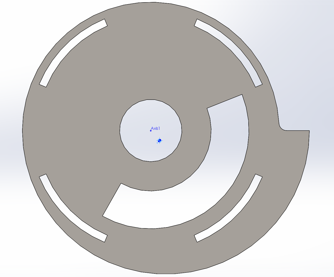
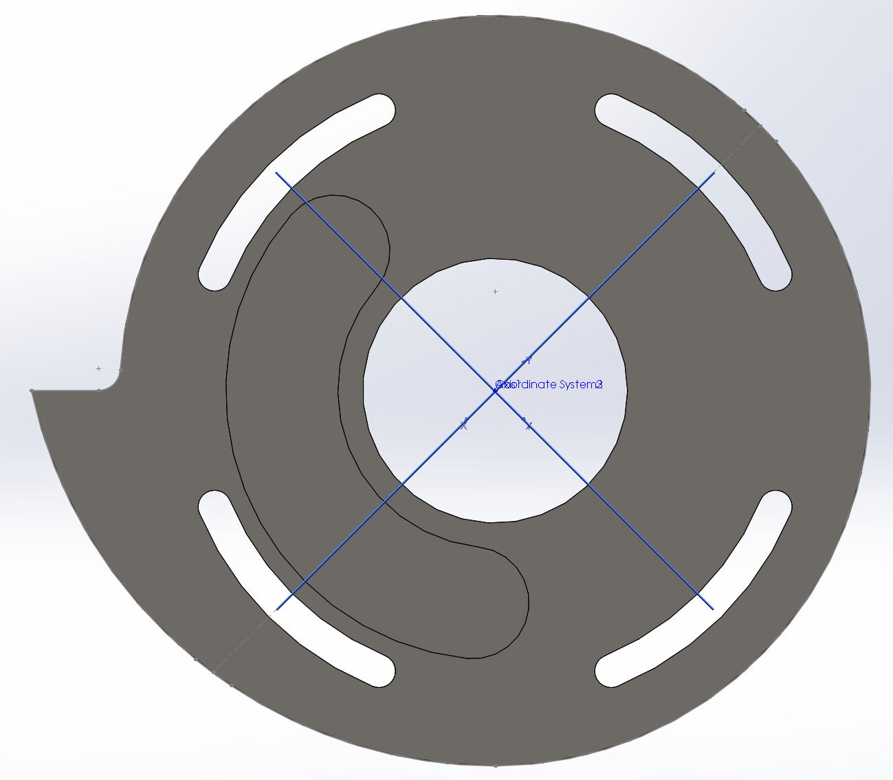
It was hard. This one didn’t have the center of mass centered, even with the giant pocket. This version also was scrapped early enough along that I hadn’t even bothered rounding any of the corners to prevent stress buildup. The real issue here was how long I initially modeled the sweep of the tooth - you can see even near the lower left tab there’s extra material from the tooth - definitely unnecessary. For v2, I tried modeling the entire rim as a spiral, attempting to add some weight to the back, as well as adding a pocket in the “excess tooth material” section to lighten that. I managed to get the center of mass centered, but still wasn’t happy - the pockets were removing a pretty large amount of material, and the wall thicknesses between various points was getting pretty small. The bore in the middle also wasn’t really as big as I would have liked, so this design was also shelved. I can do better. I also wanted to explore having just a pocket rather than a fully-cut-through design, which would improve aerodynamics slightly, as well as aesthetics. Though, come to think of it, having a hole like that in a drum spinning at $16000\ rpm$ would probably have produced an ABSURDLY loud noise. And drained the battery in seconds.
When designing the pockets, there’s a few things to keep in mind - you need it to be larger than the tooth itself, since it’s closer to the center, but on the other hand there’s also the tradeoff of strength - make it too big and you lose strength (as well as energy storage).

Finally, v3 is where I was finally happy. This was after a few hours of trying and starting and trying again, tweaking different geometries slightly, pushing and pulling. All of this was roughly based on the shape of Hypershock’s tooth, just in the single-tooth version. Incidentally, Riobotz has a really cool paper on the design of Touro Maximus’ (old) single tooth drum here. Unfortunately, since we were trying to interface nicely to a circular tube, we couldn’t just replicate it. However, we had the benefit of being able to make a pocket.
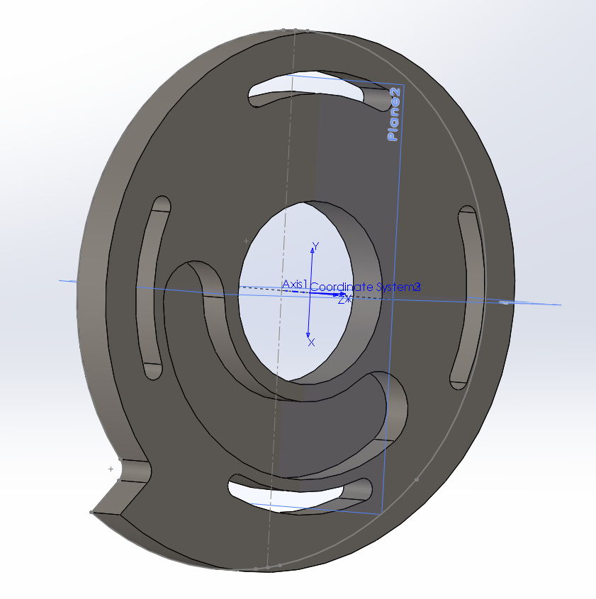
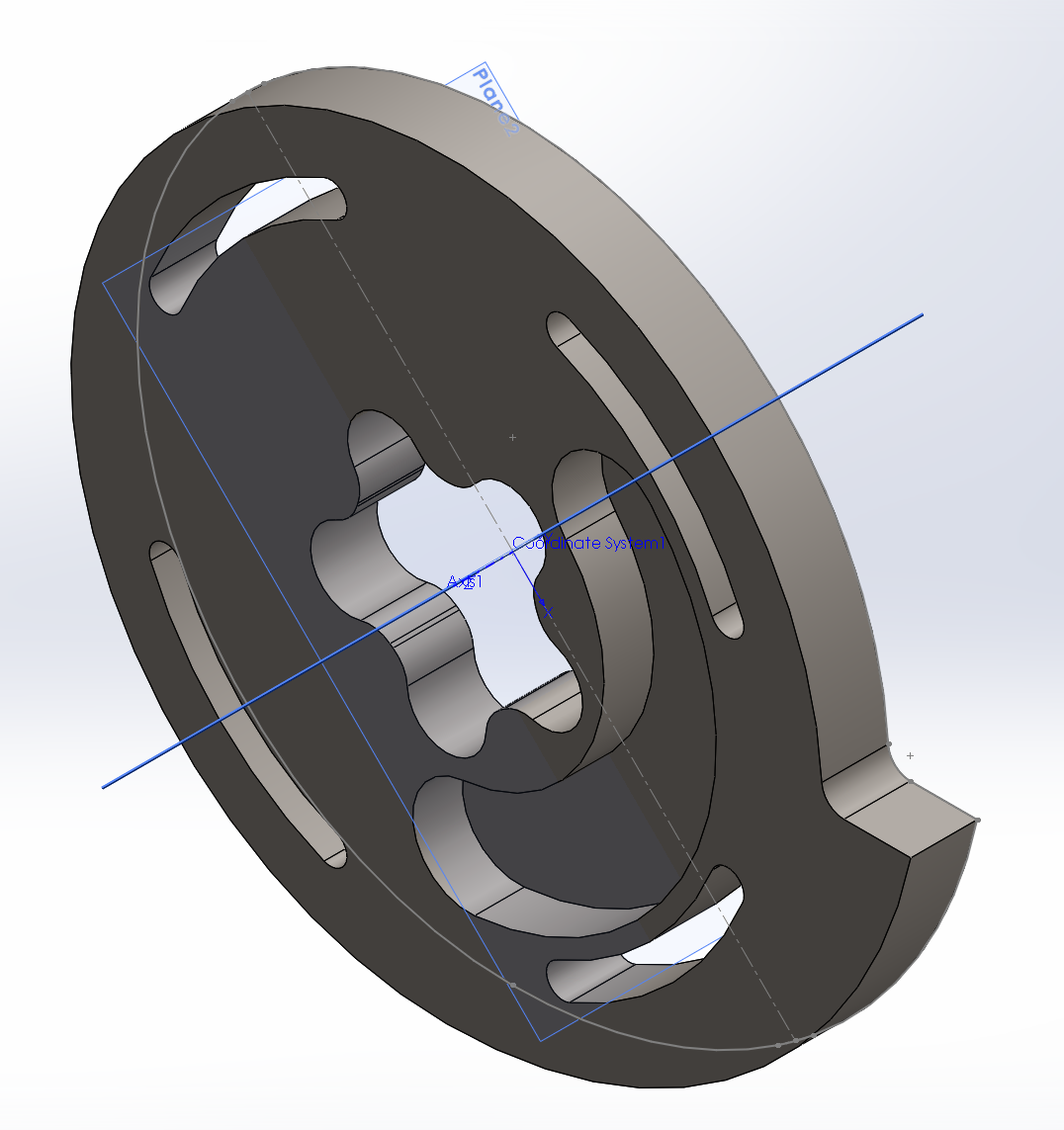
Finally, after a solid day of CAD, tweaking parameters to get it just right, we wound up with a pocket that was matched nicely to the tooth. SolidWorks reported the center of mass to about 0.0002” off-center, which is well within machining tolerances, so I’ll call it good enough. You’ll also notice some extra planes at 45 degrees - those were for creating a user-defined coordinate system for writing the CAM program - more on that later.
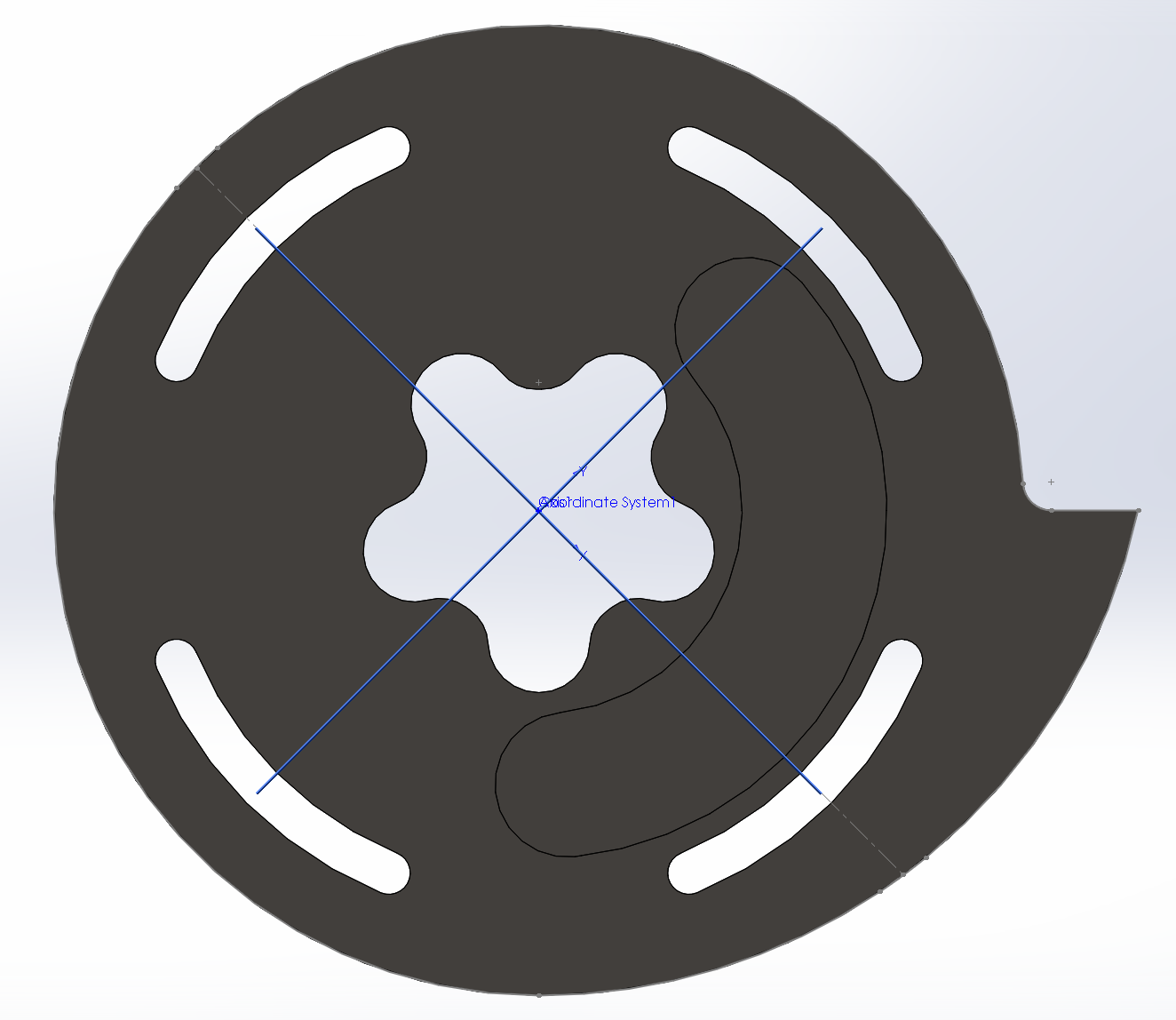
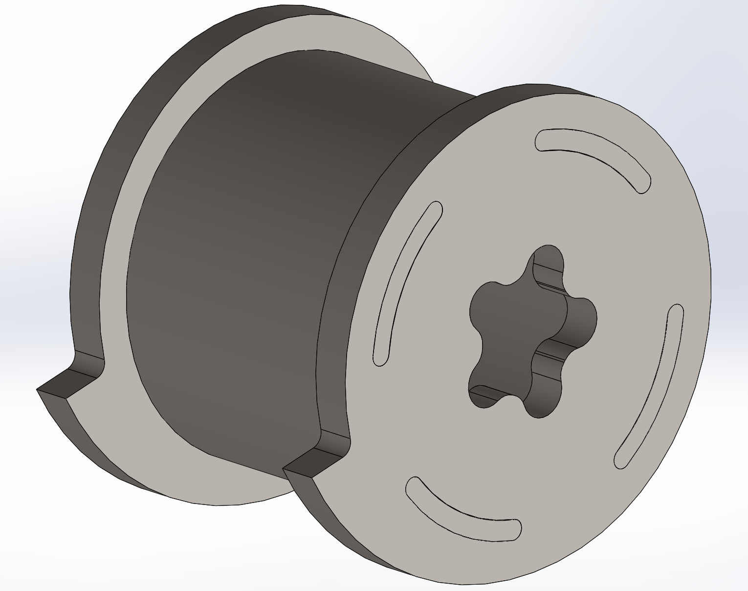
Next, I added in the Flower Power Transfer Spline™//Rebecca: Or Silly Spline™. You may be curious why I went with this as opposed to say, any other normal power transfer mechanism? Well, great question! We wanted a combination of high torque transfer so it wouldn’t slip under high startup torque or hits, as well as no sharp angles to minimize stress concentrations and aid in ease of machining (so keyways are out). We couldn’t put the pulleys directly on the drum, there wasn’t space (the 4140 tube wouldn’t be thick enough for the v-belts we wanted to use), so I would machine a pulley out of aluminum with the mate to this spline CNC’d into the end. Hypershock uses a similar system for holding their S7 plates to the aluminum core (though with the addition of bolts). We decided against bolts to, again, minimize stress points. We’d hold the two together with preloaded thrust bearings. Also, the aluminum pulley and another aluminum endcap which sat on the other side would have bearings pressed into them - achieving a press fit tolerance is a lot easier on aluminum than S7 tool steel that undergoes heat treating :P
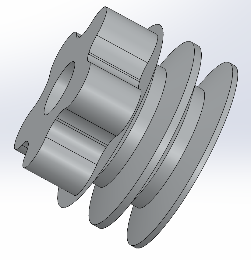
With that done, I quickly whipped up the tube holding them together as well as the other side, which was just a different configuration of the first endcap part.
And finally, add the aluminum bits and complete the assembly
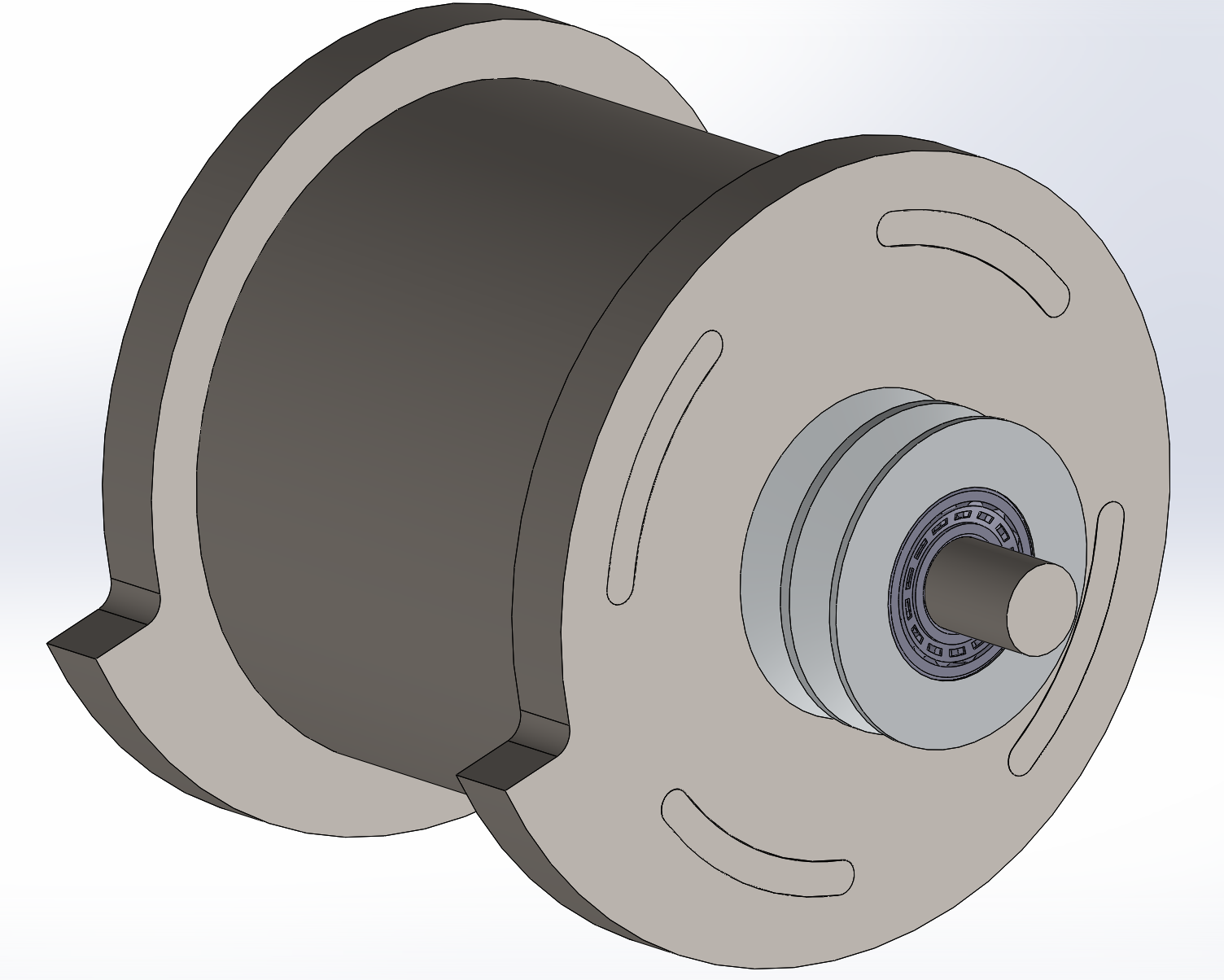
Now, an aside on bearing selection: this was really hard. We desire both super high speed ($16000 rpm$) AND super high impact resistance (enough internal surface area to not brinell on a hit). We quickly narrowed to some sort of needle bearing, tapered roller bearing, or spherical roller bearing, due to the dramatically increased surface area thanks to the rollers as opposed to balls. Many bots (Tombstone and Nightmare, for example) use giant oil-impregnated brass bushings for their weapons, but those have tremendous friction at higher speeds - anything above $5000\ rpm$ is pushing it for bushings. So, we eventually settled on Timken 22205 Spherical Roller Bearings, rated to a maximum speed of $17220\ rpm$ and max load of $11400\ lbs$ dynamic (max speed isn’t listed on this spec sheet, but it’s listed on the catalog pdf, page 66. Since these were spherical roller bearings, they had the additional benefit of aligning perfectly without any fancy machining. One of the secondary members of the team did a bunch of really fancy calculations to help with the bearing selection:
A further aside: one thing that came up with bearing selection is trying to estimate the losses we would experience at speed - is our bearing going to dissipate 10 kW and melt? Through a bit of research, it seemed like that wouldn’t be the case - the bearings would dissipate a few tens to hundreds of watts, and ditto on the belt. However, air resistance actually becomes a tremendous factor at these sorts of speeds (tip speed of $\sim 430\ mph$ at the theoretical max speed). Not being fluid dynamics simulation experts, we turned to some empirical data - as luck would have it, Will Bales tested Hypershock’s max-speed power requirements the day before I started considering this, and found it to be $19\ kW$ at $\sim 10000\ rpm$. We’re spinning about 1.5 times faster (almost identical diameter, Hypershock’s diameter is about a quarter inch larger), but importantly, Hypershock had 4 teeth vs our 2, and also has slightly wider teeth at 7/8 in vs 3/4 in (both about an inch in radial dimension). Based on the equation for drag, air resistance goes up by $Av^2$, so multiplying the area by 0.43 but multiplying $v$ by 1.5 leaves us at almost exactly the same power input.
And finally, an aside on welding: To our knowledge, no one has ever welded S7 to any other steel in a combat application. We wanted to do this to secure the endcaps to the tube in an efficient manner while minimizing stress points. Luckily for us, Tomas, one of the shop guys in Area 51 also happens to be a PhD student in materials science with an interest in metallurgy. We decided to contract out the welding and heat-treating to him, and he also helped us with selection of the tube material for weld-compatibility. Tomas’s basic guide to welding to S7: Welding 4150 works great with perhaps a bit of preheating up to the 130 C range, using 4150 filler rod. Welding 4140 is less desirable (carbon content is worse, matches worse), and requires preheating up to the 400 C range, using 4140 filler rod. In either case, huge power is needed for good weld penetration, so we planned on using N52’s $\sim 200A$ MIG welder, the most powerful welder available to us. Trying to weld 4130 or any other steel with similar or lower carbon content was generally not going to turn out well.
To tide you over until next week’s post on our giant Prius motor, enjoy these videos of the future, when we tested the S7 to 4140 welding process and results:
FOOTNOTES
- Tooth engagement is basically the battlebots term for “feed per tooth” in machinists terms. Basically, if you’re spinning really fast, you’ll tend to saw and not bite. This can be alleviated by minimizing the number of teeth - in our case, just a single tooth to maximize the speed we can get and still get sufficient tooth engagement. We set a target of half an inch, mostly just based on some guesstimations. At a maximum ramming speed of 12 mph, this means we can spin at about 16k RPM.